
RTD

RTD
THERMOCUPLE
THERMOCOUPLE

THERMOCOUPLE circuit

THERMOCOUPLE BASICS


Temperature measuring devices have been in existence for
centuries. The age-old mercury in glass thermometer is still used today and
why not? The principle of operation is ageless as the device itself. Its
operation was based on the temperature expansion of fluids (mercury or
alcohol). As the temperature increased the fluid in a small reservoir or bulb
expanded and a small column of the fluid was forced up a tube. You will
find the same theory is used in many modern thermostats today. In this
module we will look at the theory and operation of some temperature
measuring devices commonly found in a generating station. These include
thermocouples, thermostats and resistive temperature devices.
Thermocouples (T/C) and resistive temperature devices (RTD) are generally
connected to control logic or instrumentation for continuous monitoring of
temperature. Thermostats are used for direct positive control of the
temperature of a system within preset limits.
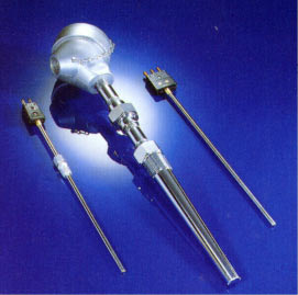
Resistance Temperature Detector (RTD)
Every type of metal has a unique composition and has a different resistance
to the flow of electrical current. This is termed the resistively constant for
that metal. For most metals the change in electrical resistance is directly
proportional to its change in temperature and is linear over a range of
temperatures. This constant factor called the temperature coefficient of
electrical resistance (short formed TCR) is the basis of resistance
temperature detectors. The RTD can actually be regarded as a high
precision wire wound resistor whose resistance varies with temperature. By
measuring the resistance of the metal, its temperature can be determined.
Several different pure metals (such as platinum, nickel and copper) can be
used in the manufacture of an RTD. A typical RTD probe contains a coil of
very fine metal wire, allowing for a large resistance change without a great
space requirement. Usually, platinum RTDs are used as process
temperature monitors because of their accuracy and linearity.
To detect the small variations of resistance of the RTD, a temperature
transmitter in the form of a Wheatstone bridge is generally used. The circuit
compares the RTD value with three known and highly accurate resistors.
RTD using a Wheatstone Bridge
A Wheatstone bridge consisting of an RTD, three resistors, a voltmeter and
a voltage source. In this circuit, when the current
flow in the meter is zero (the voltage at point A equals the voltage at point
B) the bridge is said to be in null balance. This would be the zero or set
point on the RTD temperature output. As the RTD temperature increases,
the voltage read by the voltmeter increases. If a voltage transducer replaces
the voltmeter, a 4-20 mA signal, which is proportional to the temperature
range being monitored, can be generated.
As in the case of a thermocouple, a problem arises when the RTD is
installed some distance away from the transmitter. Since the connecting
wires are long, resistance of the wires changes as ambient temperature
fluctuates. The variations in wire resistance would introduce an error in the
transmitter. To eliminate this problem, a three-wire RTD is used.
The connecting wires (w1, w2, w3) are made the same length and therefore
the same resistance. The power supply is connected to one end of the RTD
and the top of the Wheatstone bridge. It can be seen that the resistance of
the right leg of the Wheatstone bridge is R
that the resistances of the wires cancel and therefore the effect of the
connecting wires is eliminated.
RTD Advantages and Disadvantages
Advantages:
• The response time compared to thermocouples is very fast œ in the
order of fractions of a second.
• An RTD will not experience drift problems because it is not self-
powered.
• Within its range it is more accurate and has higher sensitivity than a
thermocouple.
• In an installation where long leads are required, the RTD does not
require special extension cable.
• Unlike thermocouples, radioactive radiation (beta, gamma and
neutrons) has minimal effect on RTDs since the parameter measured
is resistance, not voltage.
Disadvantages:
• Because the metal used for a RTD must be in its purest form, they
are much more expensive than thermocouples.
• In general, an RTD is not capable of measuring as wide a
temperature range as a thermocouple.
• A power supply failure can cause erroneous readings
• Small changes in resistance are being measured, thus all connections
must be tight and free of corrosion, which will create errors.
• Among the many uses in a nuclear station, RTDs can be found in the
reactor area temperature measurement and fuel channel coolant
temperature.
Failure Modes:
• An open circuit in the RTD or in the wiring between the RTD and
the bridge will cause a high temperature reading.
• Loss of power or a short within the RTD will cause a low
temperature reading.
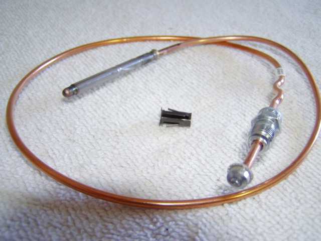
Thermocouple (T/C)
A thermocouple consists of two pieces of dissimilar metals with their ends
joined together (by twisting, soldering or welding). When heat is applied to
the junction, a voltage, in the range of milli-volts (mV), is generated. A
thermocouple is therefore said to be self-powered. Shown in Figure 3 is a
completed thermocouple circuit.
A Thermocouple Circuit
The voltage generated at each junction depends on junction temperature. If
temperature T1 is higher than T2, then the voltage generated at Junction 1
will be higher than that at Junction 2. In the above circuit, the loop current
shown on the galvanometer depends on the relative magnitude of the
voltages at the two junctions.
In order to use a thermocouple to measure process temperature, one end of
the thermocouple has to be kept in contact with the process while the other
end has to be kept at a constant temperature. The end that is in contact with
the process is called the hot or measurement junction. The one that is kept
at constant temperature is called cold or reference junction. The relationship
between total circuit voltage (emf) and the emf at the junctions is:
Circuit emf = Measurement emf - Reference emf
If circuit emf and reference emf are known, measurement emf can be
calculated and the relative temperature determined.
To convert the emf generated by a thermocouple to the standard 4-20 mA
signal, a transmitter is needed. This kind of transmitter is called a
temperature transmitter.
Simplified Thermocouple Temperature Transmitter
The temperature measurement circuit consists of a
thermocouple connected directly to the temperature transmitter. The hot and
cold junctions can be located wherever required to measure the temperature
difference between the two junctions.
In most situations, we need monitor the temperature rise of equipment to
ensure the safe operation. Temperature rise of a device is the operating
temperature using ambient or room temperature as a reference. To
accomplish this the hot junction is located in or on the device and the cold
junction at the meter or transmitter
Typical Thermocouple Circuit
Thermocouple Advantages and Disadvantages
Advantages:
• Thermocouples are used on most transformers. The hot junction is
inside the transformer oil and the cold junction at the meter mounted
on the outside. With this simple and rugged installation, the meter
directly reads the temperature rise of oil above the ambient
temperature of the location.
• In general, thermocouples are used exclusively around the turbine
hall because of their rugged construction and low cost.
• A thermocouple is capable of measuring a wider temperature range
than an RTD.
Disadvantages:
• If the thermocouple is located some distance away from the
Note
measuring device, expensive extension grade thermocouple wires or
compensating cables have to be used.
• Thermocouples are not used in areas where high radiation fields are
present (for example, in the reactor vault). Radioactive radiation
(e.g., Beta radiation from neutron activation), will induce a voltage
in the thermocouple wires. Since the signal from thermocouple is
also a voltage, the induced voltage will cause an error in the
temperature transmitter output.
• Thermocouples are slower in response than RTDs
If the control logic is remotely located and temperature transmitters
•
(milli-volt to milli- amp transducers) are used, a power supply
failure will of course cause faulty readings
.
Failure Modes:
An open circuit in the thermocouple detector means that there is no path for
current flow, thus it will cause a low (off-scale) temperature reading.
A short circuit in the thermocouple detector will also cause a low
temperature reading because it creates a leakage current path to the ground
and a smaller measured voltage.
Thermal Wells
The process environment where temperature monitoring is required, is often
not only hot, but also pressurized and possibly chemically corrosive or
radioactive. To facilitate removal of the temperature sensors (RTD and TC),
for examination or replacement and to provide mechanical protection, the
sensors are usually mounted inside thermal wells